Multiple Motion Index Drives
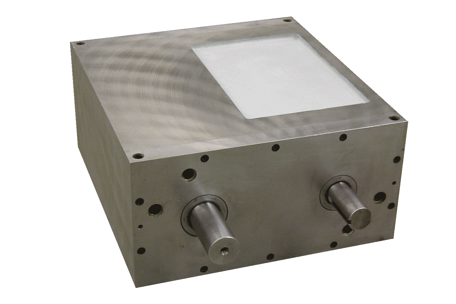
These drives combine two Cyclo-Index mechanisms in a multiple motion housing to provide speed decreasing gears off of the output, allowing you to obtain particular revolutions or motions. One set of elements controls horizontal movement while the other set controls vertical movement. Various horizontal/vertical ratios are available.
- Pick-n-place index drive – creates 1/2-revolution output.
- Walking beam index drive – obtains square or rectangular motion.