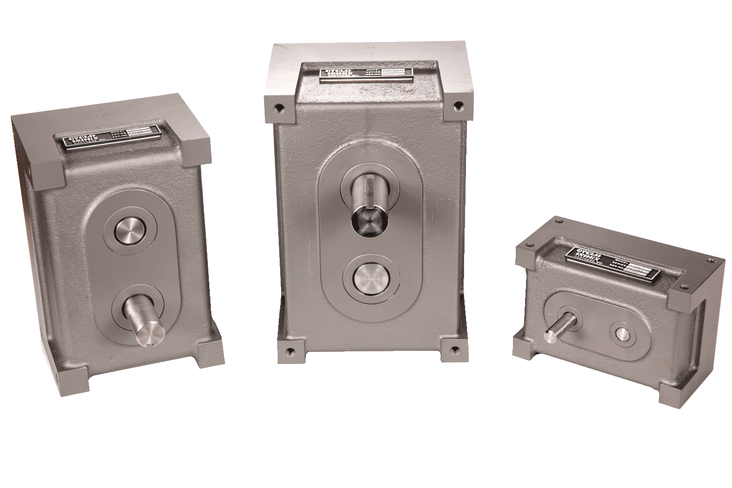
mechanical indexers, indexers, drives, cam, dial tables, driven, mechanical, motion, control, cycly-index, cyclo, index

Basic Motion Indexing Chart
 
  Basic motion index drive dimensions (in inches)* 
Series A
Dia.
Shaft
Keyway
B C D E F G H I J K
Size
L
0800 0.250
0.249
1/16 x 1/32 3-1/4 2-1/4 1-1/2 3/4 1-1/8 1 3/16 1-1/8 5/16 #6-32 2-7/8
1600 0.500
0.499
1/8 x 1/16 6-1/2 4-1/2 3 1 2-1/4 2 3/8 2-1/4 5/8 5/16-18 5-3/4
2400 1.000
0.999
1/4 x 1/8 9 6 4-1/2 2 3 3 1/2 3-1/2 3/4 3/8-16 8
2800 1.250
1.249 
1/4 x 1/8 10-1/2 7 5-1/4 2-1/2 3-1/2 3-1/2 1/2 4-1/4 3/4 3/8-16 9-1/2
4000 1.500
1.499
3/8 x 3/16 15 10 7-1/2 3 5 5 3/4 6 1 1/2-13 13-1/2
5200 2.000
1.999
1/2 x 1/4 19-1/2 13 9 4 6-1/2 6-1/2 7/8 7-1/4 1-1/4 5/8-11 17-3/4
6400 2.500
2.499
5/8 x 5/16 24 16 10 5 8 8 1 8 1-1/2 3/4-10 22
 
NOTES: Mounting hole "K" dimensions are standard for holes in Side 3. Standard mounting hole sizes and locations are available on optional sides. Rotation arrows show relative rotation of input and output shafts. Units can be operated in either direction of rotation.
 
*Use only certified prints for installation. CAD Blocks are available.

  Shaft Configurations
For horizontal mounting:
For vertical mounting:

Ordering Information
Basic index drive designations are identified as follows:
A--Series number (i.e. 0800, 1600, 2400, 2800, 4000, 5200, 6400)
B--Number of output shaft indexes per cycle of the input shaft.
C--Shaft configuration.
D--Input shaft indexing time in degrees.
E--Whole or fractional output shaft revolutions during input shaft indexing time.
NOTE: Optional shaft lengths and/or mounting holes must be specified with the order.

 
Basic Motion Indexing Charts
  Output Revs 1/8, 1/6 Output Revs 1/4 Output Revs 1/3 Output Revs 1/2 Output Revs 1 Output Revs 1-1/2, 2, 2-1/2  
 
Home Products Services Engineering Company
Ph: 417-358-6136   1129 W. Fairview Ave.
Fax: 417-358-8629   Carthage, MO 64836
Email Cyclo-Index